We use cookies to make your experience better. By using our site, you consent to cookies. Learn more.


Series AT-605 ATEX/IECEx Approved Magnehelic® Differential Pressure Indicating Transmitter
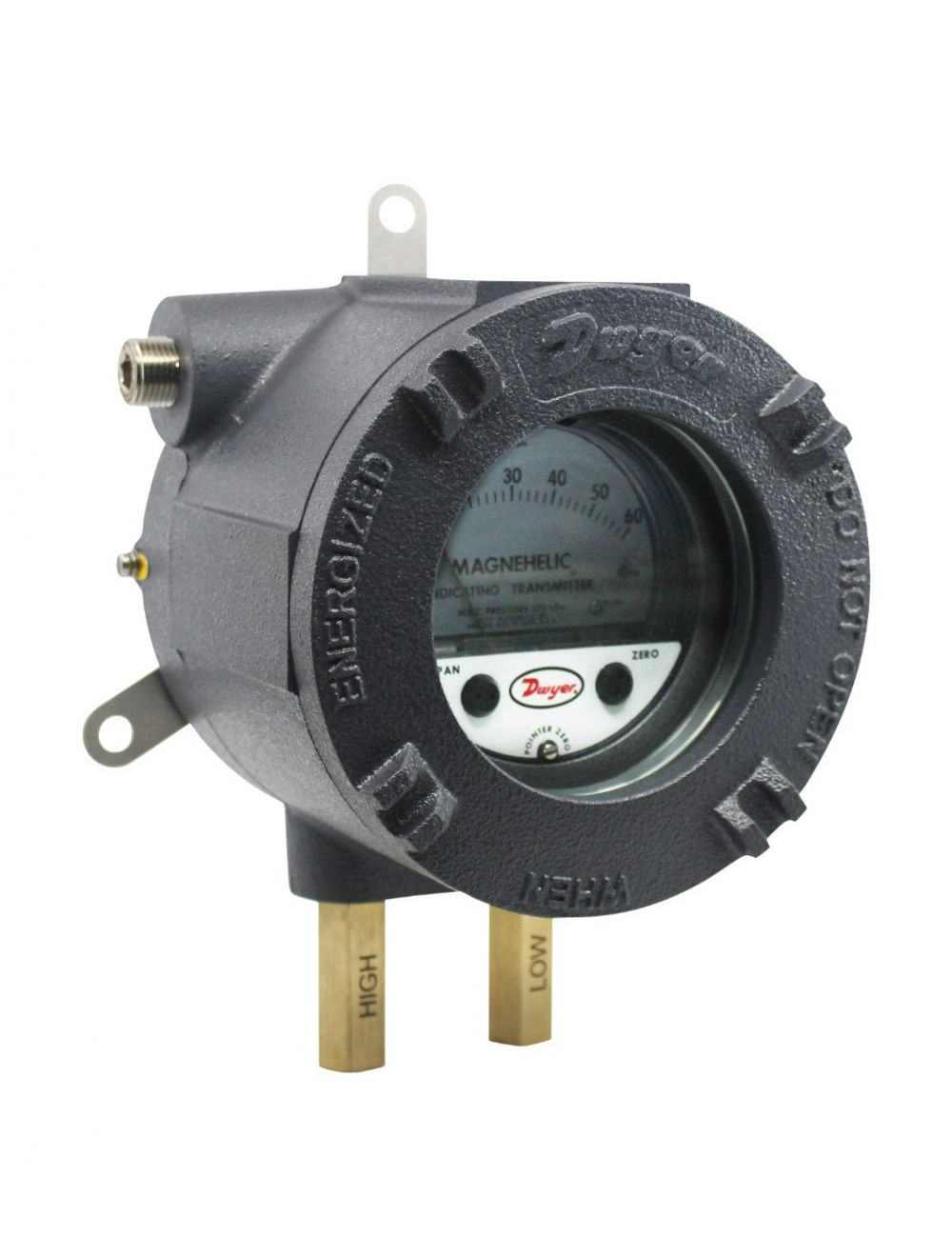
Series 605 in Flameproof ATEX/IECEx Enclosure
The Series AT-605 ATEX/IECEx Approved Magnehelic® Differential Pressure Indicating Transmitter provides for both visual monitoring and electronic control of very low differential pressure in hazardous locations. An easy-to-read dial gage is complimented by the two-wire, 4-20 mA control signal utilizing the time-proven Dwyer® Magnehelic® gage mechanical design and Series 600 transmitter technology. The two-wire design simplifies any 4-20 mA control loop powered by a 10-35 VDC supply. Flameproof enclosures are available in aluminum and can include a glass window for viewing process pressure on the gage face.
Important notes for installation:
• Cables must be fitted through 1/2" NPT cable gland or ATEX/IECEx conduit (not supplied with instrument).
• Make sure after cabling to close tight cover and cable gland, in order to maintain IP66 rating.
• Open cover only after de-energizing instrument.
Attention: Check local safety rules and warnings on unit and manual for a correct use of the instrument in hazardous areas.
Please see Series 605 for non-ATEX/IECEx approved.
Product Applications
- Monitor duct, room, or total building pressures
- Filter monitoring
- Local indication of clean room pressures with process signal sent to control room
- Hazardous area pressure measurement and transmitter
Specifications
- GAGE SPECIFICATIONS
- Service:
- Air and non-combustible, compatible gases.
- Wetted Materials:
- Consult factory.
- Accuracy:
- See page reference on catalog page.
- Pressure Limits:
- See pressure limit chart on catalog page.
- Temperature Limits:
- 20 to 120°F (-6.67 to 48.9°C) (Note: Product temperature limits differ from case).
- Size:
- 4" (101.6 mm) dial face.
- TRANSMITTER SPECIFICATIONS
- Accuracy:
- See page reference on catalog page. Includes linearity, hysteresis, repeatability.
- Compensated Temperature Range:
- 32 to 120°F (0 to 48.9°C).
- Thermal Effect:
- ±0.025% FS/°F (0.045% FS/°C).
- Stability:
- ±1% FS/year.
- Output Signal:
- 4-20 mA.
- Zero and Span Adjustments:
- Protected potentiometers on 605 face. Can access those by opening case. Allowed only in safe zone.
- Loop Resistance:
- DC: 0 to 1250 Ω max.
- Current Consumption:
- DC: 38 mA max.
- Electrical Connections:
- Screw terminal block.
- Mounting Orientation:
- Diaphragm in vertical position.
- Enclosure Rating:
- IP66 (IP65 for versions VS1/VS2/VL1).
- Housing Material:
- Aluminum.
- Finishing:
- Texture epoxy coat RAL7015.
- Process Connections:
- 1/8" NPT female brass (SS optional).
- Electrical Connections:
- Two 1/2" NPT female. Cable gland not included.
- Weight:
- 13.2 lb (6.0 kg).
- ATEX Certificate:
- INERIS 21ATEX0033X.
- IECEx Certificate:
- IECEx INE 21.0064X.
- Compliance:
- ATEX:
 0080
0080  II 2G Ex db IIC T5, T6 Gb -60°C ≤Ta ≤+50°C (T6) -60°C ≤Ta ≤+60°C (T5) II 2D Ex tb IIIC T75 °C Db;
IECEx: Ex db IIC T5, T6 Gb -60°C ≤Ta ≤+50°C (T6) -60°C ≤Ta ≤+60°C (T5) Ex tb IIIC T75°C Db.
Write Your Own Review
| Model | Description | Availability* | Price |
|---|